Arc magnets are curved neodymium magnets. They are also called arc segments or tile magnets, and each one sits in the radius of a rotor.
Mounted on the rotor of a brushless or permanent-magnet motor, an arc magnet sends a radial field across the air gap. That is what produces the torque the motor was designed for. The same shape appears in generators, sensors and loudspeakers, wherever a strong radial field has to be created in a curved space.
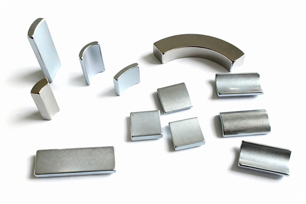
Tile Magnets (Arc Segment Magnets)
Tile magnet is the older name for the same curved rotor magnet. The shape looks like a roof tile, so the name stuck in motor shops and drawing notes. You will see all three terms used for the same part: arc magnet, segment magnet, and tile magnet. See the FAQ below for the small geometric difference between an arc and a tile.
What Arc Magnets Are Used For
An arc magnet is the essential magnetic component of a permanent-magnet motor. Each segment is bonded to the rotor yoke and magnetized radially. The rotor and stator together create a rotating field.
Outside motors, the same curved geometry appears in generators, alternators, magnetic couplings and position sensors. In loudspeakers it creates the field in a circular gap.
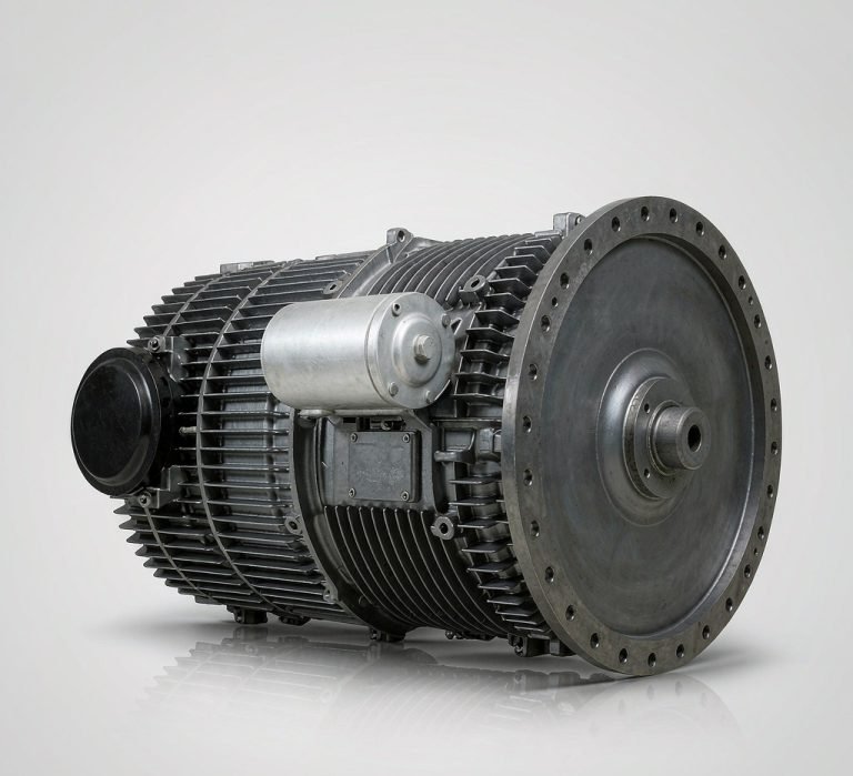 EV Traction Motors
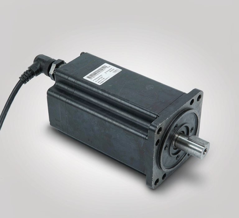 Servo & Stepper Motors
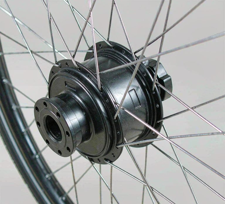 E-Bike Hub Motors
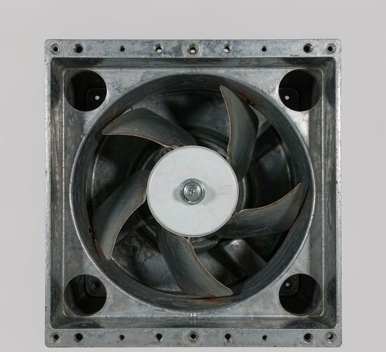 Spindle Motors, Fans & Pumps
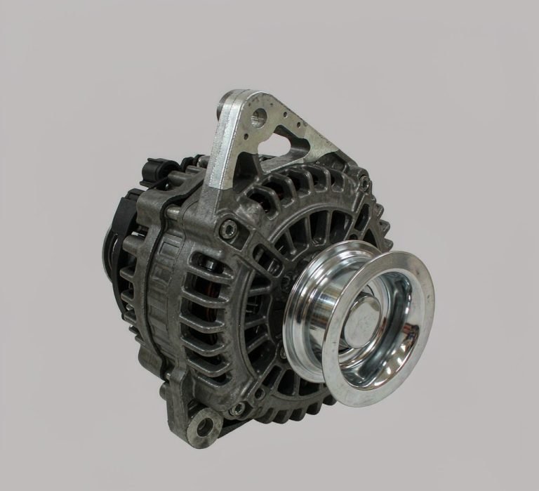 Generators, Alternators & Couplings
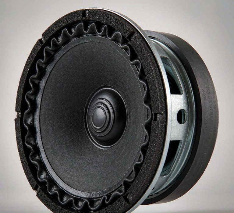 Position Sensors & Audio Drivers
How Arc Magnets Work in a Motor
An arc magnet provides a controlled radial field to the air gap. Performance depends on three things: the grade, the pole count and the magnetization pattern.
Standard grades from N30 to N38AH cover both room-temperature motors and motors that run hot. Segments can be magnetized as simple radial arcs. They can also be magnetized with a multipole pattern across the arc, which reduces cogging and harmonic losses in precision motors.
One property is easy to forget: the magnet is brittle and non-structural. It is not a load-bearing part of the rotor. The rotor yoke and the adhesive hold the segment in place, and the magnet only supplies field. A design that relies on the magnet taking shear or impact loads will fail at the interface, not at the magnet.
Specifying the Arc Geometry
Four numbers define an arc segment, and all four come from the motor rather than from the magnet. The inner and outer radius follow the rotor yoke and the stator bore, so the air gap stays uniform all the way round. The axial length follows the stack height. The arc angle comes from the pole count.
Two words get confused here, and it is the most common mistake on an arc magnet enquiry.
Pole pitch and pole arc are not the same number
The pole pitch is the space one pole occupies around the rotor: 360° divided by the number of poles. An 8-pole rotor has a pole pitch of 45°. That is usually the number people have in mind when they say the magnets are 45°.
The pole arc is the angle the magnet actually covers, and it is deliberately smaller than the pole pitch. If the magnet filled the whole pitch, neighbouring segments would touch. Flux would then short-circuit from one pole into the adjacent one across the joint, instead of crossing the air gap to the stator. Motor designers therefore work to a pole-arc-to-pole-pitch ratio, usually written α, and shorten the magnet to a fraction of the pitch. Published motor designs commonly use α between about 0.67 and 0.86, depending on the slot and pole combination and on how much cogging torque has to be suppressed.
| Rotor poles | Pole pitch (360° / poles) | Magnet arc at α ≈ 0.8 |
|---|---|---|
| 4 | 90° | about 72° |
| 6 | 60° | about 48° |
| 8 | 45° | about 36° |
| 12 | 30° | about 24° |
| 16 | 22.5° | about 18° |
| 24 | 15° | about 12° |
So a drawing described as a 45° arc for an 8-pole rotor is quoting the pole pitch, not the magnet. Order a magnet at the full pitch and the segments will touch. The motor will not produce the field the designer modelled. When you send us a drawing, tell us the pole count as well as the arc. We will confirm which of the two the angle refers to before tooling is made.
Splitting one pole into two or more segments is a separate decision, and it is common on larger rotors. Each part is easier to press and grind, eddy-current loss in the magnet falls, and the assembly can be built from smaller pieces. The cost is more parts to handle and more joints to control. Each piece covers the pole arc divided by the number of pieces. A joint between two pieces inside the same pole is not a pole boundary, so there is no short-circuit across it. Only the joints between opposed poles need the full inter-pole gap.
How Arc Magnets Are Ground
A block or tile is cut from the sintered blank into a segment of the required arc angle. It is then ground on the inner diameter, the outer diameter and both end faces.
Grinding the two concentric diameters is the critical operation. The segment has to seat on the rotor with a constant wall thickness. If the wall varies, so does the air gap, and the motor loses a fraction of its torque on every rotation.
After cleaning, the segments are coated with Ni-Cu-Ni, epoxy or Teflon depending on the environment. They are then magnetized in a dedicated fixture that produces the specified pole pattern. Every batch is checked for flux, pull and dimensions before delivery.
Tolerances That Decide Torque Ripple
Arc magnets are ground rather than pressed to shape, so tolerances can be held tight. Typically ±0.05 mm on the inner and outer diameters and the thickness, and ±0.1 mm on length and arc width. End faces are square, so segments butt together neatly around the rotor.
Two measurements matter more than the rest.
- Concentricity between the inner and outer radius. A run-out of a few hundredths of a millimetre changes the air gap. A changing air gap is torque ripple, which you hear as noise and vibration rather than see as a loss of power.
- Wall thickness of the segment. This sets the flux the segment can push across the gap. It must be consistent from part to part so the poles stay balanced.
For volume production we agree the inspection plan before the first part is made. That includes sampling frequency and the method used to measure the arc. Measuring a curved part is not the same as measuring a block. Agreeing the method up front avoids arguments at goods-in.
Grade and coating are set by the duty, not by the shape. Both are covered under motor magnets.
Handling and Assembly
Sintered neodymium chips easily, and a segment is handled several times before it is finally bonded. Every sharp edge therefore gets a controlled chamfer of 0.2 to 0.5 mm or a small radius. The chamfer on the inner corner lets the segment slide into the rotor seat without nicking. The outer corner chamfer protects the coating during handling. All edges are deburred after grinding, so no loose particles end up inside the motor.
Where segments are pressed into a tight yoke, specify a radius rather than a sharp corner at the interface. Sharp edges are the first place a brittle magnet cracks under assembly pressure. A crack that appears during pressing may not show up until the motor is running.
Bonding is the other half of the job. Provide a flat, clean seating surface and a defined adhesive gap. The glue then does not push the segment off-centre as it cures, and the bond line is the same thickness at every pole. Uneven bond lines tilt the segments and undo the concentricity achieved at grinding.
Frequently Asked Questions
How many arc magnets does a rotor need?
It depends on the pole count. A four-pole rotor uses four arc magnets and a six-pole rotor uses six. Send the pole count with the drawing and the arc magnets are ground as one matched set, so every arc magnet in the rotor carries the same pole arc.
What is the difference between an arc magnet and a tile magnet?
Nothing in principle. Both are curved segments used in a rotor radius. Tile magnet is the older name, from the shape’s resemblance to a roof tile. In practice a tile often has a smaller arc angle and a thicker wall, while arc segment is used for thinner, wider parts.
Should the magnets be magnetized before or after bonding to the rotor?
Almost always before. Magnetizing after bonding needs a fixture built around the assembled rotor, and a magnetized rotor attracts every particle of swarf and adhesive dust in the assembly area. Magnetizing the loose segment is simpler, and the pole pattern is checked before the part reaches the rotor.
How do I work out the arc angle for my motor?
Divide 360° by the number of poles to get the pole pitch. Multiply by the pole-arc ratio you want, typically 0.67 to 0.86, to get the magnet arc. Allow a small clearance between neighbours. Send us the rotor diameter, pole count, stack length and operating temperature, and we will come back with the arc geometry and grade.
Can arc magnets be made without a radial magnetization?
Yes. Multipole patterns across the arc are used in precision motors to smooth the torque curve, and some sensor and coupling designs use other orientations. The pattern has to be specified on the drawing, because it is set by a dedicated magnetizing fixture and cannot be changed afterwards.
If you are designing or quoting a motor, send us the rotor diameter, pole count and operating temperature. Our engineers will recommend the right grade, arc geometry and magnetization pattern. You can also browse the full neodymium magnet range by shape.