Encoder magnets give a position sensor a field that changes predictably as the shaft turns. Pole alignment and concentricity decide the accuracy, so both are inspected on every batch. Send the shaft diameter and the pole pattern your encoder expects.
Encoder magnets set the signal quality in a magnetic encoder. The magnet mounts on the shaft end, and the sensor IC reads the field it produces. The same magnet also decides how much stray field the sensor can tolerate before the angle reading drifts.
We make encoder magnets as diametrically magnetized cylinders and rings, and as multipole rings, in the shapes your encoder IC was designed around.
Encoder magnets are one family inside a wider set. If your part is a disc, a block or a ring that a Hall switch or a magnetoresistive sensor reads, start from sensor magnets, then come back here for the pole-count detail.
What encoder magnets do
The sensor IC sits above the shaft end and measures the direction of the field. Two sensing elements read the field along two axes. The chip takes the arctangent of the two signals and returns a shaft angle. That is the same principle behind any magnetic rotary encoder.
The chip does not measure position. It measures the shape of the field the magnet produces. A symmetric field gives a clean angle. An uneven field gives an error that repeats once per revolution.
Four things that decide how clean the reading stays
Distance. Field strength falls quickly with distance. Mount the sensor as far from the rotor magnets as the shaft layout allows. This is the most effective step, and it costs nothing.
Other materials near the sensor. Aluminium and copper have a relative permeability near 1. They block a changing field through eddy currents. A magnetic encoder reads a static field, so an aluminium plate in the flux path gives no protection at all. Austenitic stainless steels such as 304 and 316 are also non-magnetic, so swapping one for the other changes nothing.
Ferritic grades such as 430 are magnetic and will divert some flux. But a flat plate is not a shield. Shielding needs a high-permeability material that closes a path right around the sensor. A plate on one side leaves every other direction open. A steel plate also sits close to the sense magnet, takes a magnetization of its own, and adds a steady offset to the reading.
Steel plays two roles, and they pull in opposite directions. Steel behind the magnet is part of the design. A steel disc or a shallow steel cup on the back face closes the return path of the flux. More of the flux then reaches the sensor, and the reading holds up better as the gap grows. Steel in front of the magnet does the opposite. It shorts the field the sensor reads and takes a magnetization of its own. Keep the yoke on the back of the magnet. Keep steel out of the air gap.
The shaft. The shaft is steel, so it carries flux from the rotor straight to the shaft end. The hole in the plate for the shaft is a gap in any shield, and the shaft passes through it. Asymmetry inside the motor can also leave the shaft magnetized. That residual field does not vary with time, so no filter removes it.
The magnet itself. This is the part we control.
The two parameters we hold
Pole-to-pole phase deviation. Each pole should sit as close to its nominal position as we can hold it. We hold ±1.5°. That figure is for a single pole, not a cumulative error over a whole turn. Error here appears directly as angle error in the output, and encoder firmware cannot correct it.
Peak variation. Field strength should stay even from pole to pole as the shaft turns. Uneven amplitude distorts the two sensor signals and adds harmonics to the angle. We hold ±3% across the poles. We measure it on every batch, and the reading ships with the parts.
Tight values on both give you margin against the stray field the motor produces. The interference is still there. The signal is strong enough that it matters less. Both figures are our standard limits. Tighter values are available to your drawing.
Encoder magnets: shapes and grades
- Diametrically magnetized cylinders and rings
- Multipole rings, 2 to 32 pole pairs (up to 64 poles), 20 mm outside diameter and up. Pole count and outside diameter are matched to each other: the highest counts need the largest rings.
- Sintered NdFeB, N30 to N38AH
- M / H / SH / UH / EH / AH series for higher working temperatures
- Tolerances to ±0.02 mm, and ±0.01 mm where the assembly needs it
Multipole encoder magnets: 8 poles and 64 poles
Pole count sets the resolution, and it also sets how much field survives at the gap. Here are the two ends of our range. Both are rings with a 29 mm outside diameter and a 15 mm bore.
An 8-pole ring gives four electrical cycles per turn. At 0.5 mm from the ring face the peak field is about 1025 mT, and at 2 mm it still holds about 518 mT. The pole pitch is wide, about 11.4 mm, so the field does not collapse with distance. Choose it when the shaft layout leaves you little control over the gap, or when coarse angle steps are enough.
A 64-pole ring gives 32 electrical cycles per turn, so the angle resolution is eight times finer. The trade is field margin. At the same 0.5 mm gap the peak field is about 333 mT, and it falls to about 128 mT at 1 mm. Each pole pitch is only about 1.4 mm, close to the gap itself, so the field from one pole cancels against its neighbour faster as the distance grows.
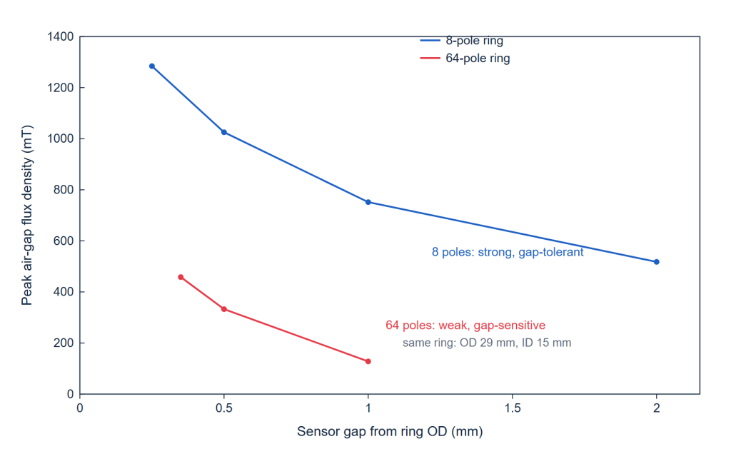
The gap sets the limit, and at 64 poles it sets it hard. We swept the full air-gap design space across three ring diameters. The results are in how tight the air gap has to be on a 64-pole encoder magnet.
How we confirm a drawing
Send us the shaft end drawing, the encoder IC part number and the working temperature. We will come back with a magnet shape, a grade and a tolerance band. For a new shape we normally make a sample in about 15 days. Each shipment goes out with a flux report and a dimensional report.
Common questions
Can I use a magnetic encoder on a motor shaft?
Usually yes. Most motor-rated encoder ICs are specified for stray-field immunity. The rotor field and the shaft still reach the sensor, so keep the sensor as far from the motor as the layout allows.
Will a steel plate shield the encoder?
Not as a flat plate. A magnetic shield has to close a path around the sensor. A plate on one side does not do that. A steel plate near the sense magnet can also become magnetized and shift the reading.
Does the grade of stainless steel matter?
Yes. Grades 304 and 316 are non-magnetic and behave like aluminium. Grade 430 is magnetic.
What tolerance do you hold on a sense magnet?
±0.02 mm as standard for this type of part, and ±0.01 mm where the assembly needs it.
Which grade should I use near a hot motor?
It depends on the temperature at the magnet, not on the motor rating. The M, H, SH and UH series cover higher working temperatures. Tell us the temperature and we will pick the grade.