Sensor magnets sit in front of a Hall or reed element and switch a circuit when something moves. The field at the sensing face is what matters, so grade, magnetising direction and the distance to the sensor face are controlled together. Send us the sensor you use and the switching distance you need.
What a Sensor Magnet Does
A sensor magnet sits opposite a Hall element, a reed switch or a magnetoresistive sensor. It gives the sensor a steady field to switch on, or to measure as a position or a speed. The magnet decides two things: how repeatable the switch point is, and how far the sensor can sit from the part it watches.
A sensor magnet is not the same as a magnet in a motor or an encoder, but it shares the same problem. The field has to be even from part to part, and it has to stay even as the temperature moves. A sensor that switches early on one unit and late on the next is a sensor that cannot be trusted.
Sensor Magnets Take Many Shapes
Any magnet a sensor reads is a sensor magnet. The shape follows the sensor and the housing, so discs and blocks are as common as rings. These are the shapes we make most.
| Shape | Usual sensor | What we hold |
|---|---|---|
| Disc | Hall switch, latch, reed switch | Flat faces, field at the switch point |
| Cylinder or rod | Angle or speed sensing | Diametric pole line through the centre, field symmetry |
| Block or square | Reed switch, proximity, linear travel | Face parallelism, squareness of the pole face |
| Ring or annulus | Position sensing around a shaft | Bore concentricity, even wall thickness |
| Arc or segment | Parts that follow a curved housing | Arc angle, radial thickness |
| Multipole ring | The magnetic scale inside an encoder | Pole count, pole pitch, pole-to-pole phase — see encoder magnets |
A multipole ring is one shape among many. It carries a row of poles around its face and acts as the magnetic scale an encoder IC counts. That format has its own page: encoder magnets.
How the Magnet Is Charged
Two magnets of the same shape behave differently depending on how they are charged. The charge direction decides the field pattern the sensor sees.
| Charge | Field pattern | Where it fits |
|---|---|---|
| Axial | North on one face, south on the other | Head-on sensing, reed switches, proximity |
| Diametric (2-pole) | North and south on opposite sides of the diameter | Rotary angle sensing: a disc or ring turns under the sensor and gives a clean sine |
| Multipole | Alternating poles around the face or the circumference | Speed and position scales; the multipole ring is the encoder case |
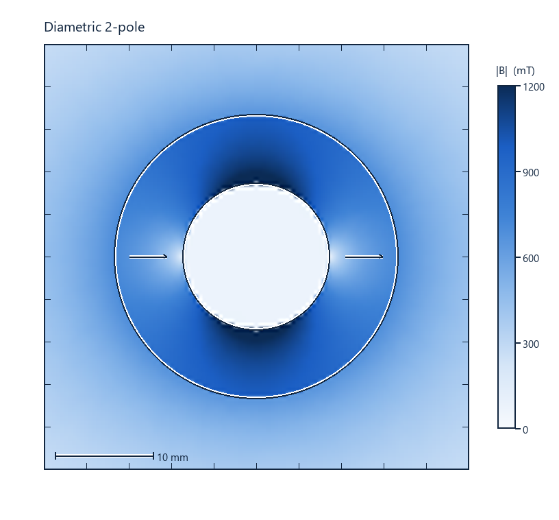 Diametric 2-pole ring. The magnet is charged straight across one diameter, so north and south sit on opposite sides. A sensor over the gap reads one clean sine for each turn.
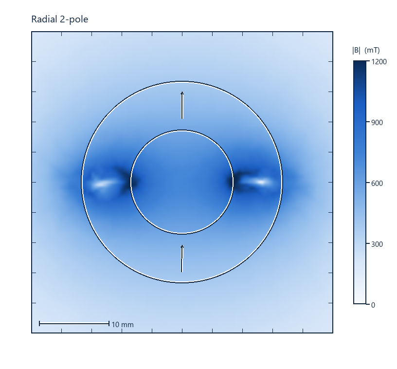 Radial 2-pole ring. The magnet is charged through the wall instead, north over the top half and south over the bottom. The outline is the same. The field pattern is not.
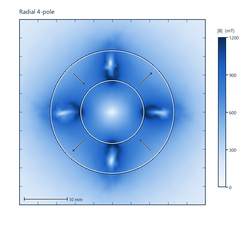 Radial 4-pole ring. Four poles step around the circumference, so two sine cycles come out of each turn. More poles pack a finer scale onto the same face.
Which Sensor Are You Matching?
The table below covers the sensor types we see most. Each row gives the shape we usually make, the grade range that fits it, and the one constraint that decides the design.
| Sensor type | Usual shape | Grade range | What decides it |
|---|---|---|---|
| Hall switch / latch | Disc or small block | N35 to N52 | Field at the switch point, operating distance |
| Reed switch | Disc, block or ring | N35 to N48 | Pull-in and drop-out field, air gap to the contacts |
| Linear or angle (Hall) | Diametric disc or ring | N40 to N52 | Field linearity across the travel, uniformity |
| Magnetoresistive (TMR or AMR) | Thin disc or block | N42 to N52 | Small, stable field; tight dimensional tolerance |
| Incremental encoder scale | Multipole ring | N35 to N52 | Pole count and pole pitch against the gap — see encoder magnets |
What Decides the Design
Four things move the spec. The air gap sets how much field reaches the sensor. The temperature sets the grade. The dimensional tolerance at the gap sets how repeatable the switch point is. The working point sets the demagnetization margin.
The air gap dominates. Field strength falls quickly with distance. Mount the sensor as close to the magnet as the housing allows. This is the most effective step, and it costs nothing. We cover the distance effect in our guide to encoder magnets, where the same rule decides how many poles you can use.
Temperature sets the grade. Use the temperature the magnet reaches in service, not the room temperature. A sensor that sits near a hot motor sees the motor's temperature, not the air. The M, H, SH and UH suffixes cover higher working temperatures. Tell us the temperature and we will pick the grade.
Tolerance becomes a magnetic tolerance. Where the air gap is short, a few hundredths of a millimetre on the mounting face moves the switch point. We work to ±0.02 mm on the gap dimensions, and to ±0.01 mm where the assembly needs it.
Steel Near the Sensor Plays Two Roles
Steel near the sensor pulls in two directions. A steel disc or a shallow cup on the back face of the magnet closes the return path of the flux. More of the flux then reaches the sensor, and the reading holds up better as the gap grows. Keep that yoke on the back of the magnet.
Steel in front of the magnet does the opposite. It shorts the field the sensor reads and takes a magnetization of its own, which adds a steady offset to the reading. A steel plate near the sense magnet can also become magnetized and shift the switch point. Keep steel out of the air gap and off the front face. The same back iron that helps behind the magnet hurts in front of it.
What We Hold on a Drawing
Where a dimension sets the air gap or the sensing distance, we work to ±0.02 mm, and to ±0.01 mm on the critical ones. Other dimensions follow the drawing. Send it and we come back with the tolerance band that fits your assembly before you commit to an order.
On every batch we also measure the things a standard dimensional report leaves out: field at the sensing point, field variation across the lot, and the magnetization direction. Ask for them by name if your sensor is sensitive to them. The reading ships with the parts.
Common Questions
Are sensor magnets always rings?
No. Most sensor magnets are discs or blocks. A ring, an arc or a rod works just as well when the housing asks for it. The multipole ring is one special case, used as the scale inside an encoder.
How far can the sensor sit from the magnet?
It depends on the field the sensor needs and the size of the magnet. Halve the gap and the field rises sharply; double it and the sensor may drop out. Tell us the sensor's minimum field and we will give you the maximum gap.
Which grade do I need near a hot motor?
Pick the grade from the temperature at the magnet, not the motor rating. That is the running temperature plus the rise from the windings and the losses. The M, H, SH and UH suffixes cover higher working temperatures.
Will a steel plate shield the sensor?
Not as a flat plate. A magnetic shield has to close a path around the sensor. A plate on one side leaves every other direction open, and a plate near the sense magnet can become magnetized and shift the reading.
What tolerance do you hold on a sensor magnet?
±0.02 mm as standard on the gap dimensions, and ±0.01 mm where the assembly needs it. Field variation across the lot we hold to a band we agree with you before the first part.
Send the drawing, the working temperature at the magnet, the magnetization direction, and the quantity. If a drawing is not ready yet, the temperature and a target size are enough to start.