How tight can the air gap be on a 64 pole encoder magnet? A 64-pole ring gives a magnetic encoder its finest angle step. It also leaves the least field margin at the sensor. The field a multipole ring produces falls fast with distance. At 64 poles the poles are narrow, so the fall is steeper than at any lower pole count. We ran a static magnetic sweep on a 64-pole ring to see how much field reaches the sensor as the gap grows, and how much a larger outside diameter buys back.
The problem
You need 64 poles for resolution. The sensor sits above the ring face at a distance your housing fixes. Two effects then fight each other. The finer the pole pattern, the weaker the field at the sensor. The wider the gap, the weaker it gets again. If the field drops toward the noise floor of the sensor IC, the angle output starts to jitter and the resolution you paid for is lost. The design question is then simple. How tight does the air gap have to be on a 64-pole encoder magnet, and when is a bigger ring the better answer?
What we checked
We built a 2D static magnetic model in FEMM. The ring is radially magnetised, bored to 15 mm, in a sintered NdFeB grade. We varied two things and held everything else constant.
- Ring outside diameter: 29 mm, 40 mm and 58 mm.
- Sensor gap from the ring face: 0.35 mm, 0.50 mm and 1.00 mm.
At the sensor radius we read the peak flux density around the whole ring and the radial waveform. As a check on the pole count, we counted the zero crossings of the radial field over one full turn. Every case gives 64 crossings, so the magnetisation pattern is correct. All figures below are model readings at 20 °C, not measured parts.
The comparison
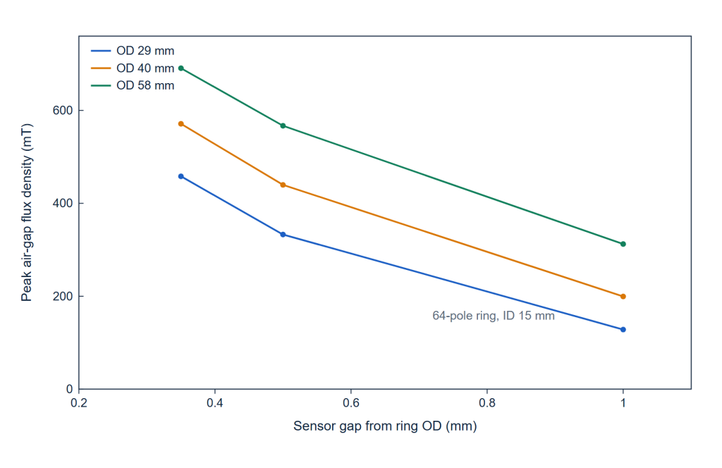
The first chart fixes the pole count at 64 and sweeps the gap. Each line is one outside diameter.
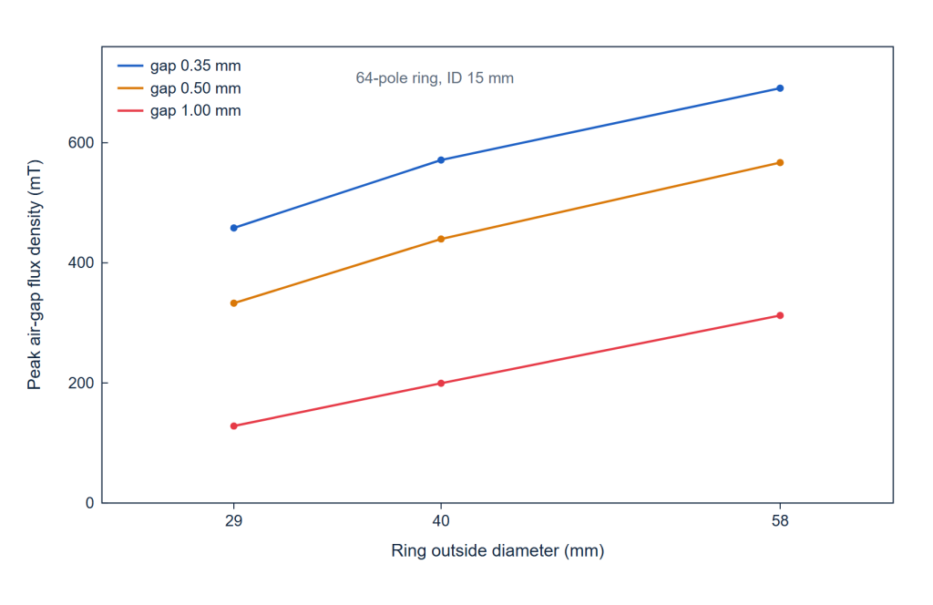
The second chart reads the same sweep from the other side. Here the gap is fixed and the outside diameter changes.
The table collects all nine runs. Pole pitch is the centre-to-centre spacing of one pole. It equals 2π times the ring radius, divided by the pole count.
| Ring outside diameter | Pole pitch | Peak field, 0.35 mm gap | Peak field, 0.50 mm gap | Peak field, 1.00 mm gap |
|---|---|---|---|---|
| 29 mm | 1.42 mm | 458 mT | 333 mT | 128 mT |
| 40 mm | 1.96 mm | 571 mT | 440 mT | 200 mT |
| 58 mm | 2.85 mm | 691 mT | 567 mT | 312 mT |
What the numbers show
The gap dominates. On the 29 mm ring the peak field falls from 458 mT at 0.35 mm to 128 mT at 1.00 mm. That is a 72% loss over less than a millimetre. The field does not fall in proportion to the gap. It falls faster, because the flux from each narrow pole cancels against its neighbours as the distance grows.
A larger diameter buys the field back. At a 1.00 mm gap, moving from 29 mm to 40 mm raises the peak field from 128 mT to 200 mT. Moving on to 58 mm raises it again to 312 mT. Each step in diameter adds about 55% at that gap. A larger ring also flattens the curve, because its pole pitch is longer. The 58 mm ring loses 45% of its field between 0.50 mm and 1.00 mm, against 61% for the 29 mm ring.
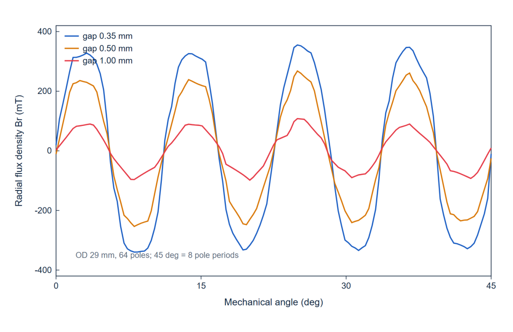
The waveform explains why. At the smallest gap the radial field is close to a square wave. As the gap opens, the corners round off toward a sine. The harmonics that carry the fine position information are the first to go, so a weak signal is also a softer one.
64 Pole Encoder Magnet: the Air Gap We Recommend
Keep the sensor gap below half the pole pitch. That single rule covers all three diameters.
- 29 mm ring. The pole pitch is 1.42 mm, so the gap should stay under about 0.7 mm. We would target 0.50 mm, where the peak field is still 333 mT.
- If the housing cannot hold 0.50 mm, do not push the gap. Increase the outside diameter instead. A 40 mm ring holds 440 mT at 0.50 mm and 200 mT at 1.00 mm. A 58 mm ring still holds 312 mT at 1.00 mm.
- Add a return yoke behind the magnet. A steel disc or a shallow steel cup on the back face closes the flux loop. The flux then returns through steel instead of through air, so less of it is lost as the gap opens. This is the cheapest gain, and it costs only the steel.
Keep the yoke on the back of the magnet. Keep steel out of the air gap and off the front face. Steel in front of the magnet short-circuits the field the sensor reads and takes a magnetisation of its own. The same back iron that helps behind the ring hurts in front of it.
What would change the answer
Four things move the gap budget.
- The sensor IC. A low-noise IC with a lower field threshold tolerates a wider gap. Ask for the minimum field on the datasheet, at the temperature the magnet will see.
- The temperature. NdFeB loses remanence as it heats. A ring sized at 20 °C can fall under the IC threshold at 120 °C. Size the gap at the hot end of the range, not the cold end.
- The pole count. Dropping to 32 poles lifts the field by about 60% at 0.5 mm and roughly 2.6× at 1 mm. Dropping to 8 poles roughly triples it at 0.5 mm. If the resolution target allows it, a lower count is the cheapest way to win back margin. See how 8 poles and 64 poles compare on our encoder magnets page.
- Eccentricity. A gap that varies around the ring adds an error that repeats once per turn. The mean gap has to sit under the recommended value, not just the nominal one.
The same trade-off appears in vehicle rotor position sensors. Magnets for e-mobility works through it inside a drive.
Frequently Asked Questions
Should the ring be magnetised radially or axially?
It follows the sensor. A radial ring presents its poles around the outside edge, which is what a sensor reading from the side wants. An axial ring presents its poles on the face, for a sensor that looks down at the ring. The two are not interchangeable, and the choice is fixed in the magnetising fixture.
How can I check the pole count on a delivered ring without a lab?
Turn the ring slowly past a Hall probe and count the zero crossings of the radial field over one full turn. Sixty-four poles give sixty-four crossings. We ran the same check on the model to confirm the pattern, and it takes about five minutes on a real part.
Sintered or bonded for a 64-pole ring?
Both are supplied, and the choice usually follows the wall thickness. A bonded ring is moulded with the pole pattern and needs no grinding on the pole face, which suits high pole counts and thin walls. A sintered ring gives more field for the same volume and holds its field better when hot. If field margin is the tight number, sintered wins; if the package is shallow and the wall is thin, bonded is worth pricing.
Send the Shaft and the Sensor Gap
Tell us the bore, the outside diameter your housing allows, and the gap the sensor sits at. We will come back with a pole count, a grade and a field figure at your sensor radius, at the temperature you give us.
Send Your Drawing